
Base plate design” is a frequently misunderstood term, particularly when discussing attachments for post-installed anchoring applications. This article explains how the concept of base plate design, which is typically understood in the context of “column base plate design,” is not necessarily relevant to fixture attachment for post-installed anchoring applications.
Typical Base Plate Design
The term base plate is commonly understood as referencing a steel plate placed beneath a column to distribute applied loads to a concrete member. The plate is assumed to act as a cantilever beam fixed at the edges of the column, defined by the geometry of a structural profile (Figure 1). If a wide-flange section is used as a column, the base plate design can be summarized as follows:
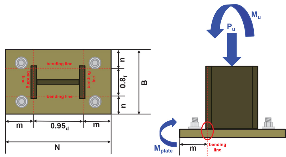
Figure 1. Column base plate design parameters.
- Select a plate length (N) and width (B).
- Check the concrete bearing capacity using these plate dimensions.
- Plate bending can be assumed to occur at the cantilevered plate sections defined by the parameters (m) and (n).
- Calculate the plate thickness (tp) via the internal bending moments assumed to occur at each cantilevered section of the plate
Column base plate design assumes the plate is rigid. In other words, the plate cross-section remains plane under loading, and the plate does not undergo any significant deformation from bending. Although no plate is ever truly rigid, it is reasonable to assume a column base plate is rigid. This is because typical column base plate geometry precludes any significant plate deformation or bending under loading. The rigid plate assumption permits the stress/strain behavior of the anchor bolts and the concrete to be modeled as elastic. An elastic stress/strain model permits a linear analysis to be used in determining the compression stress in the concrete under the plate (σconcrete), the tension loads acting on the anchor bolts (Tanchor), and the internal bending moments used to calculate the plate thickness (Figure 2).
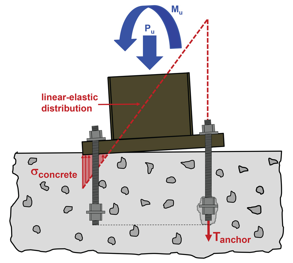
Figure 2. Rigid assumption uses a linear-elastic strain/strain model.
Typical column base plate design involves large axial compression loads, possibly acting in conjunction with an externally applied moment. Column anchor bolts are subjected to tension if the applied loads/moments create uplift on the column. It is possible for no tension loads to act on the anchor bolts if the column is subjected to pure axial compression or axial compression with a small external moment. Sometimes, column anchor bolts may only be used for erection to comply with Occupational Safety and Health Administration (OSHA) requirements. Column anchor bolt design can be predicated on the steel strength of a ductile anchor element, or on brittle failure modes such as concrete breakout. Column base plate design for shear loads can include shear load acting directly on anchor bolts, but it can also preclude shear load acting on the anchors through the use of shear lugs or embedding the column base into concrete. It is also possible that gravity load acting on the column creates enough frictional resistance between the base plate and concrete surface to preclude any direct shear load acting on the anchors.
"In these EXCEL SHEET we can calculate the WF Base Plate Design Based on AISC Manual (13th Edition) "
File Size: 553 Kb
You May Also Like These E-Books:-


No comments:
Post a Comment