
What is Direct Online Starter or DOL?
The most fundamental, economical, as well as an easy method for running a three-phase induction motor is named as the DOL starter. This starter joints three phase motors straight across the supply of three phases. The attractiveness of this kind of starter is, it can be connected straightly to the motor, and it doesn’t affect the induction motor. The Direct Online Starter consists of a protective device as well as main contacts. Let us discuss an overview of DOL.
Construction of DOL Starter
The DOL starter consists of two switches namely Green and Red where the green switch is used to start and red switch is used to stop the motor. The DOL starter comprises a circuit breaker (or) MCCB, overload relay & contactor for protecting the motor. The two switches of the motor control the contacts. The motor can be started when we shut the contact by pressing the green switch, and the full-line voltage comes out to the induction motor.
Generally, the contactors are 3-poles contactors or 4-pole contactors. For instance, a 4-pole type contactor consists of three normally open contacts and one is auxiliary or holds on contact. The three NO contacts are used to connect the induction motor to supply lines whereas the auxiliary contact is used to boost the contactor coil when the start button is opened.
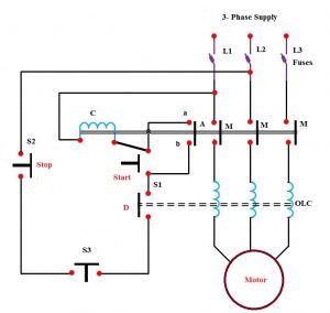
If any error takes place, then holds on contactor gets deactivated. Therefore, the DOL starter separates the induction motor from the mains supply.
With these excel Calculater we can calculate the size of DOL and Star Delta Stater Calculations
For both DOL and Star-Delta Starter input fields are:
- System Voltage (V)
- Phase (1ph/3ph)
- Type of Motor (single phase, 3-phase induction, synchronous, wound rotor etc.)
- Motor Size (HP or kW)
- Motor Code (A, B, C… -H)
- Motor Efficiency (%)
- Motor RPM
- System P.F
- Application of Motor (motor load in household application, hermetic refrigerant comperssor motor etc.)
According to above inputs, following starters components are calculated:
- Motor Torque / Current
- Motor Rated Tourque (Full Load)
- Motor Rated Tourque (Full Load)
- Motor Starting Torque
- Lock Rotor Current IL (Min)
- Lock Rotor Current IL (Max)
- Motor Starting Current
- Motor Full Load Current (Line)
- Motor Full Load Current (Phase)
Fuse (As per NEC 430-52)
- Non-Time Delay Fuse (Max)
- Time Delay Fuse (Max)
Circuit Breaker (As per NEC 430-52)
- Instantaneous Trip Circuit Breaker (Max)
- Inverse Time Circuit Breaker (Max)
Over Load Relay Setting
- Relay Min (70% of FLC Phase)
- Relay Max (120% of FLC Phase) or
- Relay Setting (100% of FLC Line)
Contactor (for DOL starter)
- Type of Contactor
- Making / Breaking Capacity of Contactor:
- Main Contactor (100% of FLC Line):
Contactor (for Star-Delta Starter)
- Type of Contactor:
- Making / Breaking Capacity of Contactor:
- Main Contactor (58% of FLC Line):
- Delta Contactor (58% of FLC Line):
- Star Contactor (33% of FLC Line):
File Size: 274 Kb
You May Also Like These E-Books:-


No comments:
Post a Comment